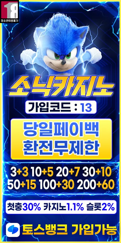
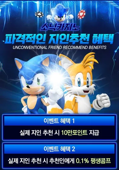
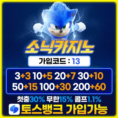
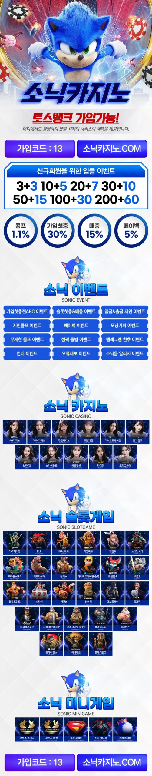
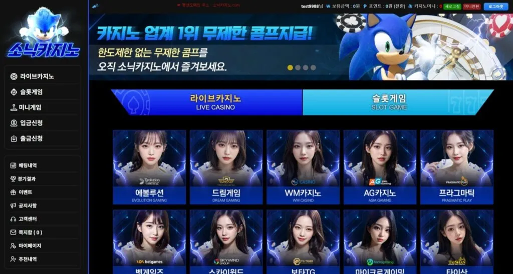
1. Frame structure
It is composed of three parts: vertical main frame, horizontal supporting truss, and frame structure.
2. Vertical main frame
The main component of the attached lifting scaffold is perpendicular to the facade of the building and connected with the attached supporting structure. A vertical frame that mainly bears and transmits vertical and horizontal loads.
3. Horizontal supporting truss
The width is the same as that of the main frame, parallel to the wall, and the height should not be less than 1.8m. A scaffold board should be set at the bottom layer, and a reversible sealed replica should be set between the building and the board. The bottom of the board should be a safety net. It mainly bears the vertical load of the frame and transmits the vertical load to the horizontal supporting structure of the vertical main frame.
4. Frame structure
The frame body between two adjacent main frames and above the horizontal supporting truss.
1) Vertical pole: set on the node of the horizontal supporting truss;
2) Longitudinal horizontal rod, horizontal horizontal rod;
3) Scissors support: set continuously, the horizontal angle is 45°~60°, and fasten with the extension end of the vertical pole or the horizontal horizontal pole.
4) Dense mesh: 2000 mesh/100cm²
5) The working layer is equipped with a 1.2m protective fence and 18cm high toe board.
5. The height of the frame
The distance from the axis of the rods at the bottom of the frame to the axis of the crossbar (ie guardrail) at the top of the frame. (Not more than 5 times the height of the floor)
6. Width of the frame
The horizontal distance between the axis of the vertical poles inside and outside the rack. (Not greater than 1.2m)
7. Support span
The distance between the central axis of two adjacent vertical main frames.
The support span of the frame in the linear arrangement of the main frame of the guide rail shall not be greater than 7m, and the support span of the frame arranged in a broken line or curve (the distance between the outer sides of the frame at the support points of two adjacent main frames) shall not be greater than 5.4m.
Broken line layout frame
Notice:
1) The material platform shall not be connected to each part of the scaffolding and each structural member, and its load shall be directly transmitted to the construction engineering structure.
2) The disconnection should be closed.
8. Cantilever height
The height of the frame above the highest support point in the attachment support structure of the frame. (Not greater than 2/5 of the height of the frame, and not greater than 6m)
9. Cantilever length
Refers to the horizontal cantilever length of the frame, that is, the horizontal distance from the vertical axis of the main frame of the frame to the vertical surface of the end of the frame.
The horizontal cantilever length of the frame shall not be greater than 2m, and shall not be greater than 1/2 of the span.
Length of overhanging section: L1
Length of anchoring section: L2
L2≥1.25L1
Note: the difference between the concept of the length of the overhanging section and the overhanging scaffolding.
10. Anti-overturning device
A device to prevent the frame from overturning during lifting and use.
11. Anti-falling device
A device that prevents the frame from accidentally falling during lifting or use.
Use the steel pipe clip to fix it after the lifting is finished, and be careful to remove it when lifting again.
12. Lifting mechanism
The power mechanism for controlling the lifting movement of the frame is electric
13.Load control system
A device that can reflect and control the load that the lifting mechanism bears during work.
14. Cantilever beam
One end is fixed on the wall-attached support to suspend the cantilever steel beam of the lifting equipment or the anti-fall device, also known as the suspension beam.
15. Guide rail
Attached to the wall supporting structure or attached to the vertical main frame to guide the scaffolding up and down rails.
16. Synchronous control device
During the lifting and lowering process of the frame, the lifting speed of each lifting point is controlled so that the load or height difference of each lifting point is within the design range.
17. Attached wall support
The wall-attached support is the attachment supporting structure of the lifting frame, which bears and transmits the load of the lifting frame, and at the same time, realizes the jam protection function under the accidental fall condition through the anti-falling device set inside it. It integrates load-bearing, anti-falling, anti-tilting, and guiding functions, and can better adapt to the verticality of the structure, the error of the reserved embedded pipe and the smaller deviation.
The wall-attached support is welded, processed and assembled by steel. The guide rail of the guide rail main frame is inserted into the guide wheel seat, and the sliding cooperation between the guide roller and the guide rail is used to restrict the main frame of the guide rail from moving up and down.
The distance between the lifting frame and the engineering structure can be adjusted by adjusting the adjusting bolts, and the adjustment range is 180±25mm.
18. Conversion device
(1) Triangle iron parts
When the exterior of the main structure is a balcony or other overhanging slabs, and the main frame here cannot be properly installed on the wall or beam, consider using triangular irons for conversion to ensure the normal installation of the wall-attached support.
(2) Spacer
When there are 200-300mm wide horizontal decorative eaves on the periphery of the structure, it is used to appropriately widen the distance between the frame and the structure to ensure the smooth construction of the structure and the lifting of the frame. There are a variety of models to choose from.
(3) Heightening parts
When there is an air-conditioning board or bay window board with a width of 300mm~600 mm on the periphery of the structure, it is used to appropriately widen the distance between the frame and the structure to ensure the smooth construction of the structure and the lifting of the frame. There are a variety of models to choose from.
(4) Hanging parts
Used for hanging the electric hoist, using M30 anchor bolts to firmly connect with the engineering structure, and transfer the load of the frame body to the load-bearing parts of the engineering structure during lifting. It is divided into ordinary hanging parts, extended hanging parts, channel steel hanging parts, and small hanging parts. Several kinds.